10 MIN READ
Optimizing Subsurface Drainage Systems
October 6, 2021
Wet, soggy fields can delay tillage, planting, spraying, and harvest operations. The removal of excess water from fields is dependent on surface and subsurface drainage. Surface drainage utilizes waterways, ditches, and other means to help direct excess water off a field and into larger streams and rivers. Subsurface field drainage occurs when excess soil profile water that seeps into historical clay or concrete tiles and modern-day plastic tubing flows into nearby streams and rivers underground. In some situations, the flow of subsurface drainage systems is reversed so water can be pumped back through the system to irrigate crops.
Potential Benefits of Subsurface Drainage
- Increased yield
- Quicker field access for springtime tillage and spraying operations
- Improvement in soil tilth
- Deeper root penetration
- Reduced compaction
- Reduced water stress on plants
- Quicker warming of soil temperature
- Improved soil conditions help promote quicker emergence and plant population
- Improved water infiltration.
- Well-designed systems can help limit nutrient loss that can occur with surface drainage.
- Lowering of salinity concentration (requires a period of years).
- Management of saline seepage from hillsides to lower field areas.
Potential Disadvantages of Subsurface Drainage
- Leaching of nitrates into the drainage system and ultimately into streams, lakes, and oceans.
- Some pesticide leaching may occur; however, this is more likely with surface drainage.
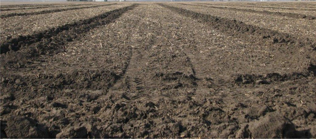
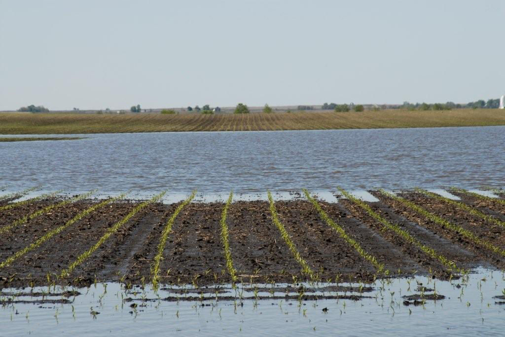
The potential for increased crop yields is the largest driver for installing subsurface drainage (Figure 1). Crop yield can be affected because wet fields prevent timely field operations, increase the potential for water related seedling diseases, kill existing crops, and cause nutrients, especially nitrogen, to become unavailable for root uptake (Figure 2). With the reduction of these factors and others through subsurface drainage, crop yields are likely to improve. Research on poorly drained soils has shown an average increase of 10 to 15% in crop yield when fields are tiled 1. Typical yield responses with adequate subsurface drainage can range from 10 to 30 bu/acre for corn and 4 to 8 bu/acre for soybean.1
A long-term northwest Minnesota subsurface simulation trial showed that without drainage, the average annual yield of spring wheat was 65% of the potential yield. With subsurface drainage, the average annual wheat yield increased to 78 to 82% of the potential yield.2
Canola potential yields can be reduced when poor drainage provides a favorable environment for canola diseases to develop. Additionally, it has been shown that canola potential yield may be reduced by 5, 10, and 20% if the canola crop is not planted by the 3rd week of May, the 4th week of May, and the 1st week of June, respectively.3
Design
Subsurface tiling designs depend largely on the topography of each field. The tile laterals feeding into a larger main tile can be laid in patterns that are parallel, herringbone, double main, or targeted (like alternating leaves on a tree branch). Regardless of design, the main and associated laterals must be of proper size to accommodate current drainage requirements plus potential expansions. The flow through the tile line is dependent on gravity; therefore, tile depth should be three to five feet deep depending on field slope, normal plow depth, and entry point into a ditch, stream, pond, or other endpoints. If the tile outlet will be lower than the exit point, a collection facility with appropriate pumping equipment will be required to direct the collected water away from the field. Pumping stations can increase the cost of a tiling system considerably; therefore, proper budgeting is necessary.
The depth and spacing determine the rate of water removal from the tiled soil. A close relationship exists between soil permeability, lateral spacing, and lateral depth. Drainage systems are generally designed to lower the water table at least 0.5 feet within 24 hours.4 Comparatively, soils with finer soil particles (loams and clays) require laterals to be closer while soils with coarse particles (silts and sands) can have laterals spaced farther apart.1 Coarse silt or sand soils may need a protective envelope surrounding the drainage tube to help prevent soil particles from flowing into the tube with the water.1 Your local Natural Resources Conservation Service (NRCS) office should be consulted for design, soil, and water conservation policy information, and possible financial assistance for surface and subsurface drainage systems.
Managing Nitrate Leaching
Nitrate leaching into tile laterals is the main concern of subsurface drainage because of environmental and water quality issues. Shallower tile lines, water control structures, bioreactors, two-stage ditches, cover crops, and saturated buffers are methods to help manage nitrate leaching.
Shallower Tile Lines
Laterals placed shallower and closer together have shown an ability to reduce the nitrate concentration in tile water by removing less water.5 The system essentially keeps the overall water table higher than deeper tile; however, the shallower tiles remove water quicker. Caution is required as laterals must be placed deep enough to avoid potential crushing by heavy equipment. Minnesota and Illinois research has shown a nitrate load reduction of about 20% when lines are installed at 3 feet compared to 4 feet.5 The purpose of subsurface drainage is to help reduce surface runoff. Shallow placed tile lines may result in a minimal decrease in runoff; therefore, phosphorous and sediment movement could remain an environmental factor. Nitrate seepage into the groundwater could still be a factor if seepage is occurring below the tile lines. Additionally, denitrification may increase with shallower lines because saturated soil in the root zone may create anaerobic conditions that support denitrifying bacteria that convert nitrates to nitrogen gas which helps prevent nitrates from reaching tile and surface water.5
Wider Tile Spacing
Increasing the distance between tile lines, which reduces the amount of water removed, can potentially reduce the total amount of nitrate flowing into the drainage system. Environmental Protection Association (EPA) computer modeling has shown that the nitrate load can be cut by about one-third when line spacing is increased from 40 to 50 feet.5,6
Water Control Structures
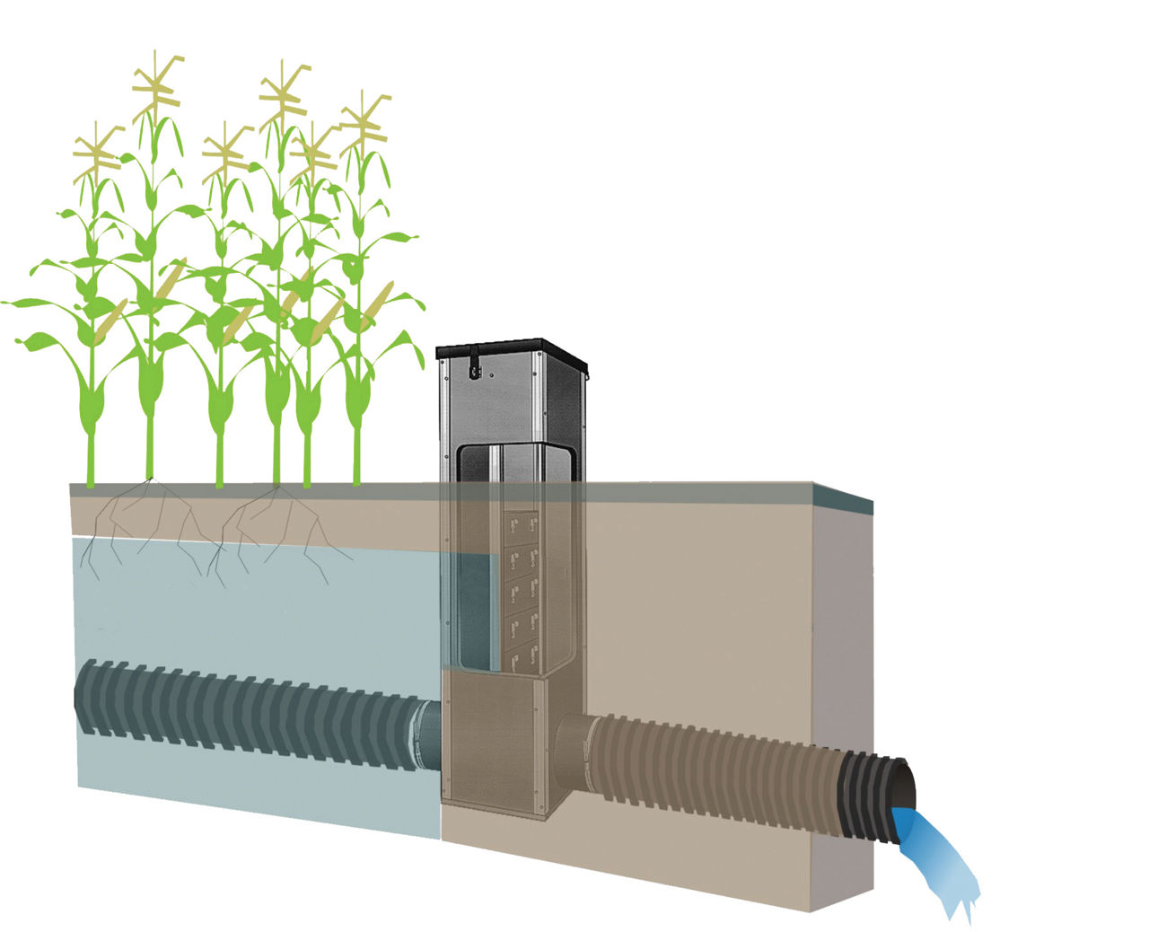
Water control structures placed in the main, sub-main, or lateral drain can be used to vary the depth of the drainage outlet to manage the depth of the water table and flow of nitrates (Figure 3).7 The structure is lowered in the spring and prior to harvest so the drain can flow freely to reduce soil water and raised after planting and spring field operations to store water for crop use. Research has shown that the reduction in the amount of nitrates in the tile water ranges from 15 to 75%, depending on location, climate, soil type, and cropping practices.1,7 Drainage water management reduces flow volumes in the system and may help reduce nitrate leaching.8 Rock inlets can be used to replace open inlets to reduce water flow to drainage inlets and limit sediment from entering the system.
Bioreactor Systems
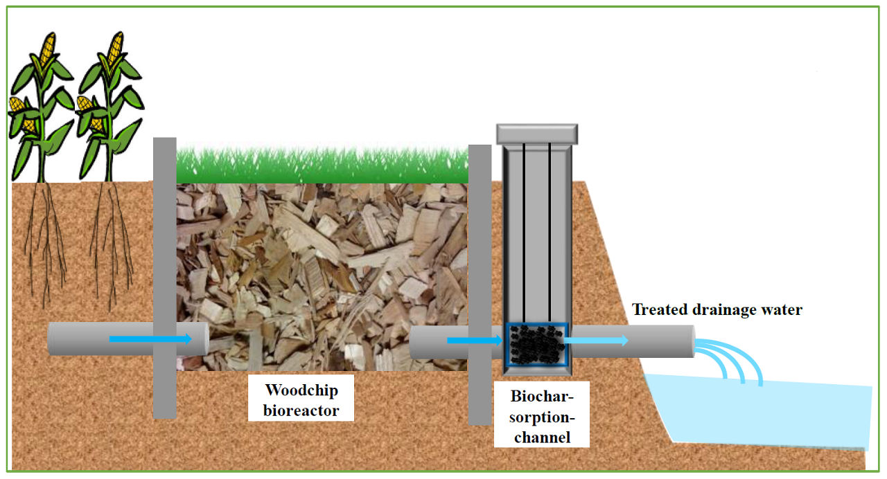
Bioreactor systems use subsurface trenches filled primarily with woodchips to filter drainage water before it leaves the field and flows into the drainage ditch or stream. The wood chips serve as a substrate for denitrifying bacteria to convert nitrate to nitrogen. Based on Iowa, Illinois, and Minnesota research, bioreactors typically remove about 15 to 60% of the nitrate load in a system per year.9
Under research is the addition of a separate “biochar” filtering structure after the woodchip structure and just prior to water exiting the system into the ditch or stream (Figure 4). Biochar is a charcoal-like, carbon-rich product that can absorb and hold nutrients such as nitrogen and phosphorous. Periodically, the biochar can be removed and spread upon the field prior to the planting of a crop. During the growing season, the nutrients are released from the biochar and utilized by the crop.10
Saturated Buffer
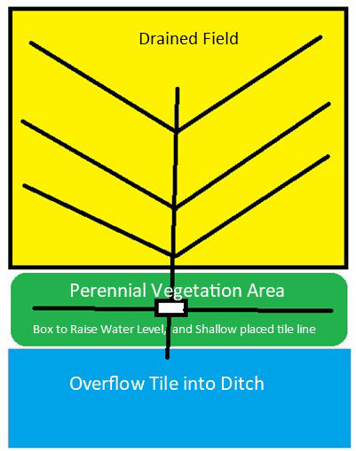
The purpose of a saturated buffer area is to help “siphon” crop nutrients such as nitrates and phosphorus from subsurface drainage before it empties into the collecting ditch or stream. Saturated buffers have been attributed to removing an average of 42% of the nitrate.11
Saturated buffers are areas of perennial vegetation (at least 30 feet wide) located between cropland and the subsurface drainage outlet (ditch or stream) (Figure 5). The area should be lower than the adjacent cropland to avoid inundation.11 The system involves the installation of a water flow structure, installation of shallow placed drainage tubes about one foot below the surface, and the planting of perennial vegetation over the shallow drainage tubes. The structure serves as a dam and raises the water level from the main tile and redirects the water into the shallow tile line where the roots of the perennial vegetation can absorb nutrients from the drainage water. In essence, the system provides subsurface irrigation to the perennial vegetation.
After seeping from the saturated buffer tile, the soil within the buffer must permit a slow lateral water movement to the ditch or stream. Loam soils provide the best movement, high clay soils may restrict movement, and sandy soils can be too quick. Additionally, at least 1.2% of organic matter is needed in the top 2.5 feet of the buffer soils to encourage nitrification.11 Wood chips mixed into the soil prior to planting the vegetation can provide additional organic matter.11 The ditch or stream bank should be stable and not exceed 8 feet in height.10
Two-Stage Ditches
Drainage Water Recycling
Recycling involves the construction of a reservoir for water being removed through subsurface drainage and then applied back to the field through irrigation. The potential to reduce nitrate load with recycling is considerable. However, investment costs can be steep because of the reservoir size requirement and irrigation equipment. As an example, a 3-acre pond with a depth of 11 feet would be required to store 4 inches of runoff and subsurface drainage from 100 acres. The cost of implementation may be more practical for higher value crops such as vegetables and fruits.5
Wetland Reestablishment
The cost of establishing a wetland can be high if the current cropland is removed from production. Nitrates within a wetland are managed by several means.
- Denitrification occurs when nitrate in the water is changed to gaseous nitrogen and released back into the atmosphere.
- Plant life within the wetland uses nitrate from the water for growth.
- Total amount of drainage water is reduced by seepage into groundwater, through plant transpiration, and evaporation.5
Wetland effectiveness is better during warmer months because of plant growth; however, the nitrate load is likely to be the highest during cooler spring-time temperatures. An average of about 20 to 50% of the nitrates can be removed annually through wetland establishment.5
Other Containments
In many situations, surface water enters above-ground risers connected to subsurface tile lines. Water flowing into the risers can carry sediment, nutrients (especially phosphorous), and possibly pesticides. Grass filters, blind inlets, and woodchip filter socks are potential means of trapping and filtering contaminants from the flowing surface water.12
Grass planted around the inlet can help filter the contaminants before the water flows into the inlet. The disadvantages are that grass replaces productive crop acreage and the grass may be killed if ponding occurs during excessively wet periods.13
Blind inlets are subsurface structures built in low-lying field areas that filter the water through soil, limestone gravel, geotextile, and a sand-gravel mixture. Perforated tubes are placed within the limestone layer to intercept the filtered water and direct it into tiles leaving the field. The structure is covered with soil which allows for the planting of crops.13
Filter socks are circular cloth tubes filled with woodchips and aluminum sulfate (alum) that surround the tile riser. The socks capture sediment and nutrients (especially phosphorous) before flowing into the inlet. The socks require annual replacement and maintenance. Minimal acreage is removed from production with this concept.13
Manure
Best management practices should be followed when applying manure to tiled fields. Manure can easily flow with surface water and enter drainage risers taking the contaminated water to streams and rivers. The filtering concepts for risers above may help reduce the negative factors associated with applying manure. Avoiding applications just prior to expected rain can help reduce manure contamination of tile water.13
Additionally, soil cracks in fields parched by high heat and drought can be direct avenues for contaminants from manure to reach tile lines; therefore, manure application to such fields should be avoided. Tilling the field prior to an application may help close the cracks and allow the soil to be more of a filter.14
Subsurface Irrigation
In some areas, a well-planned subsurface drainage system can be used for subsurface irrigation. Though not needed in most of the Midwest, irrigation can help maximize yield in potential in areas that typically have low rainfall or have light colored or sandy soils. Sub-irrigation generally requires tile lines that are closer together and a source of water to pump back through the tile line to raise the water table during dry periods. The water source could be a pond of sufficient size that is the endpoint for water flowing out of a tile line. An appropriate structure, such as pictured in Figure 3, is required at the end of the tile line to stop the flow of water out of the field and be used to increase the water table as water is pumped back into the line from the pond.
Initial investment cost can be high because of the need to construct a pond with adequate size to collect and hold the drainage water that will ultimately be used for irrigation. Additionally, the tile cost increases because more tile is required for narrow spacings, there is a need for a pump to introduce the drainage water back into the system, and there is the cost of removing productive acres to build the pond.
Summary
Successful subsurface drainage is dependent on a well-designed system that fulfills current needs, is designed for future expansion, follows conservation guidelines, and observes local drainage policy and laws.
Sources
1Scherer, T., Sands, G.R., Kandel, H., and Hay, C. 2015. Frequently asked questions about subsurface (tile) drainage. AE1690. North Dakota State University. https://www.ag.ndsu.edu/tiledrainage/documents/faq-about-subsurface-tile-drainage.
2Jin, Chang-xing , and Sands, G.R. 2004. Simulation of spring wheat response to subsurface drainage in Northwest Minnesota. American Society of Agricultural and Biological Engineers, St. Joseph, Michigan.
3Simundsson, A., Grieger, L., and Chorney, H. 2016. Development of a decision-support tool for economic considerations of on-farm surface water. Subsurface drainage as a water management strategy: adaptive, economic, and environmental considerations. For: Manitoba Agriculture, Manitoba. Final Report, Research Report. Growing Forward 2. PAMI. https://www.gov.mb.ca/agriculture/environment/soil-management/pubs/subsurface-drainage-as-a-water-management-strategy.pdf.
4Subsurface Drainage (NCRS 606) AgBMPs. The Ohio State University. https://agbmps.osu.edu/bmp/subsurface-drainage-nrcs-606.
5Christianson, L.E., Frankenberger, J., Hay, C., Helmers, M.J., and Sands, G. 2016. Ten ways to reduce nitrogen loads from drained cropland in the Midwest. Publication C1400. University of Illinois Extension. http://draindrop.cropsci.illinois.edu/index.php/i-drop-impact/ten-ways-to-reduce-nitrogen-loads-from-drained-cropland-in-the-midwest/.
6Yuan, Y., Bingner, R.L., Locke, M.A., Theurer, F.D., and Stafford, J. 2011. Assessment of subsurface drainage management practices to reduce nitrogen loadings using AnnAGNPS. Applied Engineering in Agriculture. American Society of Agricultural and Biological Engineers, St. Joseph, MI, 27(3):335-344. https://cfpub.epa.gov/si/si_public_record_report.cfm?Lab=NERL&dirEntryId=221663.
7Frankenberger, J., Kladivko, E., Sands, G., Jaynes, D., Fausey, N., Helmers, M., Cooke, R., Strock, J., Nelson, K., and Brown, L. 2006. Questions and answers about drainage water and management for the Midwest. Drainage Water Management for the Midwest. WQ-44. Purdue University. https://www.extension.purdue.edu/extmedia/wq/wq-44.pdf.
8Illinois drainage guide. http://www.wq.illinois.edu/
9Christianson, L. and Helmers, M. 2011. Woodchip bioreactors for nitrate in agricultural drainage. PMR 1008. Iowa State University. http://www.leopold.iastate.edu.
10Capturing and recycling excess nutrients from farmland. Illinois Sustainable Technology Center. Prairie Research Institute. University of Illinois. https://www.istc.illinois.edu/research/pollutants/agricultural_chemicals/capturing_recycling_excess_nutrients_from_farmland/.
11Janes, D. What are saturated buffers. 2018. National Laboratory for Agriculture and The Environment: Ames IA. United States Department of Agriculture (USDA) Agricultural Research Service. https://www.ars.usda.gov/midwest-area/ames/nlae/news/what-are-saturated-buffers/.
12Frankenberger, J. Two-stage ditches. Purdue University. https://engineering.purdue.edu.
13Keep your nutrients in your field. 2018. National Laboratory for Agriculture and The Environment: Ames, IA. United States Department of Agriculture (USDA) Agricultural Research Service. https://www.ars.usda.gov/midwest-area/ames/nlae/news/keep-your-nutrients-in-your-field/.
14Ballweg, M., Erb, K., and Pape, A. Best management practices to keep nutrients in the field and out of the tile. University of Wisconsin. https://sheboygan.extension.wisc.edu/files/2018/10/Best-Managment-Practices-to-Keep-Nutrients-in-the-Field-and-Out-of-the-Tile.pdf.
Additional Source:
Roy, D., Grosshans, R., Puzyreva, M., and Stanley, M. 2018. Nutrient recovery and reuse in Canada: Foundations for a national framework. International Institute for Sustainable Development (IISD). https://www.iisd.org/sites/default/files/meterial/nutrient-recovery-reuse-canada.pdf.
1008_S3
Disclaimer
ALWAYS READ AND FOLLOW GRAIN MARKETING AND ALL OTHER STEWARDSHIP PRACTICES AND PESTICIDE LABEL DIRECTIONS.